Tier suppliers and manufacturers of vehicles outside the passenger car market have long been pioneers in the adoption of new technologies. AMS examines some of the latest innovations and techniques being used to cut costs and improve product quality
Manufacturing technology has grown exponentially over the past two decades, as many auto industry segments have adopted methods aimed at reducing labour and material costs while increasing productivity, efficiency and component quality. Yet while some industry segments are quick to jump into new manufacturing technology, the US automotive industry – consisting primarily of the so-called Detroit Three automakers – has been slow to adopt such methods. There are a number of reasons for this: the current systems dictate separate manufacturing plants and lines for every vehicle model; there is union resistance to any technology that could eliminate jobs; and carmakers just can’t adjust their manufacturing methods with sufficient speed to adopt new technologies.
As the larger automotive OEMs continue to cut production and staff, more Tier One and Tier Two suppliers are assuming the role of technological innovators in areas such as R&D, new product development, and tooling and production. They are also providing complete assemblies such as instrument panels, door and roof panels, and other kitted components.
Smaller, leaner and more nimble than their OEM customers, these suppliers are realising the benefits of new manufacturing technologies, with investments reaping returns in shorter periods of time. As such, they are more willing to spend substantial amounts of money to implement new manufacturing technologies, while OEM carmakers rely on the same companies to help them reduce their own costs. Compare processes at automotive OEMs with those producing construction machinery and equipment, snowmobiles, all-terrain vehicles (ATVs), tractors, and lawn and garden equipment.
Barring the amount of capital investment required to update the technology, there is no apparent reason why, in this era of cost-cutting, carmakers could not take advantage of the improved efficiencies represented by these new techniques.
 Welding robots
Automation plays a variety of roles within vehicle manufacturing. Robotics became popular early on, but it was the advent of advanced software that gave robotics a true edge in reducing carmakers’ unit labour content. Union leaders, though, didn’t like robots. The image of union workers being replaced by machines struck at the heart of unions and kept the implementation of robotics to a minimum. While OEMs faced pressure to maintain workforce levels, Tier One suppliers quickly adopted the technology, taking advantage of the production efficiencies and eventually becoming leaders in the field. With vehicle assembly requiring up to 5,000 resistance spot welds, the priority was placed on automating the welding process. Delphi Technologies is one such innovator in the field of automated welding, with its Deformation Resistance Welding (DRW) technology. Developed using the company’s Lean manufacturing Engineering programme, DRW ticks all the boxes: increased efficiency, productivity and quality, while being perfectly suited for high-volume applications such as automotive manufacturing.
Itself a one-time subsidiary of General Motors, Delphi in turn proceeded to spin off its DRW technology by creating SpaceForm, the first company under the Delphi Technologies umbrella. Located in Troy, Michigan, and in partnership with Edison Welding Institute, the new company served as conclusive proof that smaller, more nimble suppliers could better produce technology free from the red tape of larger companies. Essentially, SpaceForm’s DRW technology is based on two electrodes passing current through the metal to be welded, creating heat that forces the two pieces together. Instead of relying on welding rob material, or filament, to connect the two surfaces, the bond comes from the mating surfaces themselves. The ideal application is with tubular structures for vehicles, as well s in processes that require issimilar materials to be welded together for totally new structural approaches. Tubular structures, reports SpaceForm, result in lighter and more fuel efficient vehicles, as opposed to those using stamped metal.
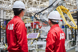
 Like welding, robotic painting allows manufacturers to realise advantages over manual operations, including improved application and reduced concerns over health and safety issues, with employees removed from the paint booths. However, it isn’t always easy to automate paint applications in tight spaces. A leading supplier of industrial robots for paint applications (as well as welding, handling, assembly, and machine tending), ABB offers the IRB 52 for painting in areas where limited space is a key consideration. The robot is compact and can be mounted on the fl oor, ceiling or wall, at any angle. Despite it’s reduced size, ABB claims it has a large working envelope and great agility. The IRB is suitable for a variety of paint applications, including 1k, 2k and water-borne paints. The 7 kilogramme payload meets most requirements for single-, dual- or triple-gun solutions, while it can work in different operation modes – automatic line with conveyor tracking or manual operation with a shuttle table or turntable. The IRB also features a backward-bending operation, which, together with a reach of 1.45 metres, means only one robot is required for two spray booths when they are installed face-to-face. “The IRB 52 is the ideal robot for painting in general industry,” says Stone Shi, Product Manager for ABB. “It provides an affordable, professional and highquality painting solution.”
Military spaceframes
In January of last year, SpaceForm and Michigan’s GraviKor announced a strategic development and licensing agreement to develop vehicle spaceframe technology for security and military markets. The multi-year agreement between the two companies involves an exclusive ‘field of use’ licence for military vehicles to GraviKor using SpaceForm’s DRW technology. This allows virtually instantaneous joining of high-strength tubular components. According to GraviKor, this is key in overcoming the related costs of conventional spaceframe fabrication methods.
Jayson Pankin, New Venture Creation Specialist for Delphi, says: “DRW will be used for novel applications currently not being done because of the limitations of traditional weld technology when working with metals like aluminium. DRW will compete on a quality and total cost basis to become the preferred technology for certain high-volume products, and potentially – this is important – suspension links, instrument panel cross-car beams and engine cradles. DRW could create savings in tooling, masks and footprinting, reducing the number of work stations required.”
 Throat size
Welding has been on the leading edge of manufacturing technology advances for more than a decade. One of the biggest challenges of automating the welding process is adapting it to the thick metal plate used in the production of large construction and earth-moving equipment. At Caterpillar Work Tools in ‘s-Hertogenbosch, The Netherlands, automated welding of thick metal plate has helped the company attain new efficiency levels, using a robot with a 24mm throat (a 24mm in multilayer) that reduces welding times by 40 per cent compared to completing the process manually.
Such an extreme throat size is quite exceptional and can only be achieved in multiple passes with the welding torch. The correct deposition rate places some stringent restrictions on the process, while to prevent the wire from burning out, the arc’s power density cannot exceed 1.5kJ. Caterpillar’s manufacturing process provides one of the few examples of welding automation used in the fabrication of thick metal plate, simply because of the physical size of the system required and the large investment this represents, a major hurdle to many manufacturing companies. Valk Welding supplied Caterpillar Work Tool’s system, including the programming application.
Automating this process has had tremendous benefits, improved process times translating into cost savings. Hand-welding the blade onto a large digging bucket used to take more than eight hours, and due to a shift change mid-assembly, the component would always cool down and require reheating (for the additional welding to be completed). According to Valk, the welding robot reduces the time needed for this job by 60 per cent.
While vehicle manufacturers might have reservations about using robotic welding in applications that require custom work, Caterpillar Work Tools found that product standardisation across the product range (itself consisting of components made in small-batch, customised runs), played into their hands. For example, the teeth that are welded onto the bucket blades are the same between products. To solve the difference in positioning, Valk installed a programmable system to create a subroutine for welding a tooth, applying this subroutine wherever a tooth needed to be positioned. That saved a lot of programming, with the offline programming application providing the flexibility needed to fabricate multiple variants. Additionally, the complete welding process could be simulated offline.
Moulding the liner
New surface finish technology is another area of rapid development. Sunroof linings, for example, require a combination of high strength with low weight. In this case, the lining uses a sandwich structure: a spacer layer of honeycombed cardboard between outer layers of glassmat, the product built up within the mould. Once arranged, this is then sprayed with polyurethane (PUR) and pressed into shape. The finished component is then manually unloaded, with the mould having to be cleaned and sprayed with release agent after each cycle.
 Working with German machinery manufacturer KraussMaffei, which supplied the production system, a Korean automotive components supplier has recently started serial production of these sunroof linings. In developing the new production system, KraussMaffei looked to automate as many production stages as possible. Designed as a rotary table with three processing stations, the first station positions fixing frames holding the preassembled honeycomb spacer and glassmats in the mould, the frame holding the sandwich structure taut to prevent wrinkles and creases. In the second station, a robot manipulates a KraussMaffei airless spray mixing head, saturating the glassmats with PUR. In the third station the component is pressed into its final shape and a robot handler unloads it from the mould. As the PUR reaction mix now contains an internal release agent, the need for cleaning and spraying of separate release agents has been removed. Automating the system has reduced labour costs and increased high-quality productivity.
PUR skin
Introduced almost four years ago, KraussMaffei has made constant improvements to its SkinForm PUR technology. Originally developed for small parts, such as cup holders, produced by automotive parts supplier Fisher Automotive Systems, SkinForm technology combines Reaction Injection Moulding (RIM) and injection moulding by applying a decorative PUR ‘skin’ over an injectionmoulded substrate. Automated systems for this technology include unmoulding the moulded core of one material, with a PUR mixing head injecting a two-component softfeel covering fed from a KraussMaffei RIM-Star MiniDos PUR machine. KraussMaffei reports that although originally used with smaller parts, the system is now being more widely used with larger parts. In addition to the Korean case study, Cadence Innovation, located in Liberec, Czech Republic, is using the system to produce car door interior trim panels.

Rapid prototyping (RP) came onto the scene in the early 1990s, with the advent of stereolithography (SLA). At that time, SLA played only a limited role in manufacturing, creating prototype parts that were really only good for presentation purposes. While it gave manufacturers a better idea of what the fi nal part would actually look like, these demonstrators couldn’t be tested or used like the actual part, though it was better than trying to imagine the physical part from a drawing or even a 3D computer model. As RP technology developed, materials developed into what became known as rapid manufacturing (RM). Today, these processes use ‘additive’ technology, meaning parts built up layer by layer using a variety of powdered polymers and metals that use a laser to solidify the material. This process not only produces prototypes, but actual parts ready for end use. There are several additive fabrication technologies in use, including fuse deposition modelling (FDM) and selected laser sintering (SLS) that use powdered metals. This additive fabrication (AF) technology is becoming increasingly popular as the equipment used to ‘print’ the parts becomes more versatile and cost effective.
Graham Tromans, Manager of the Rapid Manufacturing Consortium at Loughborough University, UK, says that the primary benefi ts of AF technology are the savings in time and cost. In one case study done for Land Rover, the RM Consortium was able to achieve an 80 per cent reduction in time and 60 per cent reduction in cost through the use of rapid prototyping, primarily due to the better designs, new process opportunities, prove-out of new concepts, a reduction in re-tooling, and design risk reduction, versus 3D CAD. “Often, when using CAD to produce a part, the engineer will say, ‘Oh, I didn’t expect it to be like that,’ which is a good reason for rapid prototyping.” The RM Consortium has made both RP and RM parts for the McDonnell Douglas F-18 Hornet, plus the company has engineered a full-size engine. “We had trouble getting designers to use RP and RM,” says Tromans. However, one of the best reasons for using additive technologies is that the complexity of a part’s shape is never an issue, as it might be with subtractive (machining) technology, or using injection moulding for a component.
LFI Inmold
Additionally, KraussMaffei now offers a new Inmold painting process for producing long fibre injection (LFI) parts with high-gloss surfaces. A paint layer is sprayed directly onto the surface of the mould, where a spray mixing head then applies a barrier coat. The LFI layer is poured into the mould, which is then closed and clamped. The result is a high-strength, fibre-reinforced part with an outstanding high-gloss surface.
The new LFI Inmold painting process is already in operation at Harita Seating Systems Limited of Hosur, India, where it is being used to produce tractor engine covers. It differs from other PUR processes in that the long glass reinforcing fibres are wetted with the PUR in the mixing head itself. One major advantage of this is the use of low-cost rovings rather than preformed glass mat.
 Where the most widely used method for achieving a high-quality surface to an LFI part was to apply the PUR/ glassfibre back to a thermoformed film inserted into the mould, the barrier coat process is an attractive alternative, particularly for projects with relatively small production volumes or with a large number of colour variants. Future applications could include the customised mass production of vehicles. When the paint is applied directly in the mould, mould surfaces will need to be of a very high quality, and polished to a high gloss. KraussMaffei produces the moulds in its Competence Center for Tooling Technologies at the production plant in Viersen, Germany.
An alternative process is to apply only the barrier coat to the LFI parts in the mould and to paint them in a subsequent process. This option is attractive to producers who already operate a paint line, like large OEMs and their suppliers. The painted or paint-ready parts can also be produced as honeycomb-core parts, as mentioned above, the additional barrier coat preventing the honeycomb core being visible on the surface. Currently, the primary application for these painted fibre-reinforced parts are commercial vehicles, buses, trucks and agricultural machinery.
Quickparts, based in Atlanta, Georgia, is a leading provider of rapid prototypes and low-volume, custom-manufactured production parts. The company uses a variety of materials for processes that include SLS, FDM and cast urethane moulding. Patrick Hunter, Vice-President for Sales and Marketing says that SLS has actually become a mainstream production process for the aerospace industry. “Since SLS allows for complete design freedom, aerospace companies have started incorporating it into their designs. As we see production volumes shrink, I think it will begin entering the auto market as a viable process.” Quickparts has built a custom-designed part used to house the wireless scanner developed to scan the surface tiles of space shuttle orbiters. Needed to locate and evaluate cracks and imperfections on the tiles lining the spacecraft’s outer skin, the challenge was that the housing needed to be built very quickly, from a production quality material that could withstand regular, extended periods of use without breaking. Quickparts used the FDM process to build the model, with the build material (production-quality thermoplastics) melted and then extruded through a specially designed head onto a platform to create a twodimensional cross section. The cross section quickly solidifi es, and the next layer is extruded upon the previous layer, with the process continuing until the model is complete. Quickparts also used this type of rapid manufacturing to produce the fi nal product. “With no need for expensive tooling, these custom-designed parts can be made quickly, inexpensively and at any time,” says Hunter. “With so much customisation, rapid manufacturing as a whole will begin gaining a stronger presence. My personal belief is that the automotive sector has not been forced to explore new manufacturing technologies. With the current economic conditions and the change in product design, rapid manufacturing may have an opening to enter the auto market.
Taking out the VOCs
Another application for tractor assembly is being used by Iowabased Plastics Unlimited for agriculture machinery producer Gehl. According to Terry Kieffer, President of Plastics Unlimited, the process uses a toolless engineering composite (TEC), which eliminates volatile organic compounds (VOCs), for a hood and cowl components. The components are produced using a proprietary process that forms the fibre glass-reinforced substrate on the back of a Class A-finish thermoformed plastic shell which features moulded-in colour for a highgloss finish. Combining thermoplastic and composite technology, the process uses up to 35 per cent soy-based resin, making for an environmentally-friendly product.
By-passing the bridge
Direct digital manufacturing (DDM) is a process that uses the digital representation of a part to produce the final product, basically from machine to direct application. This allows technicians to by-pass bridge processes, such as creating a mould or die, or any pre-machining. As opposed to subtractive fabrication, direct manufacturing technology is an additive technology, building up parts in layers with a laser, based on a CAD-sourced data set. Carl Dekker, President of Met-L-Flo, a prototyping service centre that offers stereolithography (SLA), selected laser sintering (SLS) and fuse deposition modelling (FDM), says the company has added direct digital manufacturing (DDM) to its portfolio. “These technologies are starting to find a home among the manufacturing community. We’re now using DDM on the shopfloor.”
Research effort
Boeing, EOS Electro Optical Systems, Evonik Industries and MCP HEK Tooling have recently joined with Germany’s University of Paderborn to form the Direct Manufacturing Research Center (DMRC). Signed in July 2008 by representatives of the companies and the university, the agreement commits to further development of direct manufacturing processes and systems. “Direct manufacturing offers the potential to significantly reduce parts production costs, as well as enhancing the ability to fabricate more complex and more functional component parts,” says Jeff DeGrange, Chairman of the Board of the DMRC consortium and Senior Manager of Direct Digital Manufacturing at Boeing Phantom Works, Boeing’s advanced R&D organisation.
Each of the four partner companies will contribute their core competencies to the research effort, with Boeing defining production processes and system requirements from an aerospace standpoint, and Evonik Industries producing polymer-based standard materials (plus material solutions tailored for direct manufacturing). EOS and MCP HEK Tooling are slated to provide expertise in the development of laser sinter and laser melting systems for metals and polyamides.
Scanning for accuracy
While 3D CAD or ‘solid’ modelling is relatively new, those who have discovered its advantages over 2D versions are reaping the benefits. John Deere receives many CADmodelled parts from suppliers, with one of these being a handle for the tilt steering mechanism. For reasons unknown, this was not aligning properly with its gear teeth.
John Deere initially inspected the part using a coordinate measuring machine (CMM) and determined that the parts were defective, despite the supplier insisting they had been made to specification. Nevertheless, with the failure rate on the assembly line unusually high for the tilt steering mechanism, John Deere concluded there was a need to compare the entire as-built shape to the as-designed model in order to determine the real cause of the misalignment.
The company contracted 3DScanCo of Atlanta, Georgia, to scan, inspect and verify whether or not there were defects in the parts John Deere were receiving. The company chose 3D laser scanning as the best choice for the project, due to its ability to quickly capture warping and variations in shape over the entire part. The high-resolution data captured by the Konica Minolta VIVID 91 scanner was used to generate highly accurate (within 0.002 inches) inspection reports that John Deere needed to confirm its initial findings. Comparing the resulting scan data to the as-designed CAD data supplied by John Deere, 3DScanCo generated a colour map inspection and cross section analysis that clearly showed several areas of deviation between the shape of the CAD and the actual parts, ultimately causing a misalignment in the field.
Following the release of the report, the supplier made modifications to the tooling, the second batch of handles successfully aligning with the gear teeth and allowing for proper function of the tilt steering mechanism. The scan and inspection data generated by 3DScanCo served not only to dramatically reduce the failure rate on the assembly line, but also gave John Deere’s engineers new ideas on how to model higher-quality CAD data for future parts.
The stated aims of the Direct Manufacturing Research Center, which was set up in June this year, is the signifi cant improvement of product properties, production costs and process stability of direct manufacturing methods for tools and small series parts. Being based at the University of Paderborn means the centre can ensure the close collaboration of various academic disciplines of mechanical engineering, informatics, chemistry and materials science as well as researchers from DMRC industry partners. The University’s competencies in mechanical engineering include mechanics, lightweight construction, particle technology, polymer technology and mechatronics. In chemistry they include polymer materials and interface processes, as well as computer sciences. A close collaboration is boosted by a fi rm organisational structure with close proximity of labs on the one hand and offi ces of DMRC members on the other. The four founding companies – Boeing, EOS Electro Optical Systems, Evonik Industries and MCP HEK Tooling – will invest a total of €2m in the DMRC over the contract period of fi ve years, equivalent to an annual contribution of €100,000 per company. Additionally, the University of Paderborn will contribute €600,000. The German state of North Rhine-Westphalia has also invested €1.4m to improve the University’s research infrastructure for direct manufacturing. Research at the DMRC will be led by University Paderborn professors and carried out by its technical staff and students. Seconded staff members from industry also will contribute and partly work on joint projects at the DMRC. Initial research will focus on improvement of the processes for laser sintering/melting technology for metal and plastic powder. “This consortium... will provide our students, faculties and staff members with an opportunity to learn about the newest generation of direct manufacturing technology and to contribute our competencies in this fi eld,” says Professor Dr Nikolaus Risch, President of the University Paderborn.
Production future
While manufacturing technology continues to evolve, the development and use of new processes, materials and manufacturing techniques will likely remain within consortiums, automotive suppliers and machinery producers. It is these groups that are most eager to take advantage of increased automation, improved materials and leaner processes. In fact, with OEMs demanding lower part prices and thus dramatically reducing supplier margins, cutting production costs is not a choice but a requirement if turning a profit and staying in business is the goal.
It is a sign of the times that what suppliers have known all along might well prove to be the salvation of OEMs – whatever the reason for having summarily failed to adopt this cost-cutting opportunity, bringing the technology in-house could be a key factor in their on-going fight for survival.

