As modern vehicles become more sophisticated, production testing technologies and processes need to keep up. Mike Farish looks at developments with both carmakers and tier suppliers
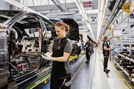
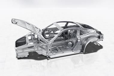
From the beginning of next year, premium carmaker Porsche intends to introduce a testing procedure for selected completed vehicles that aims to halve the time taken to audit the cars for defects ranging from surface blemishes to the the non-inclusion of required parts in the complete assembly.
According to Dr Andreas Schmidt, head of quality at the plant, this is a procedure that the company carries out on three vehicles coming down the line every day as a means of checking that quality levels are being maintained. However, until now the task has relied on purely human perception and, due to the intense level of scrutiny involved, has required up to eight hours per vehicle to complete. “We are checking the completeness of the car,” he observes.
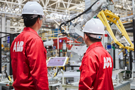
The new procedure will take just four hours and use augmented reality in which computerised data is superimposed on real world imagery viewed through a single handheld tablet computer. Discrepancies revealed by the comparison of real world and virtual data – a prime source for the latter being the company’s computer-aided design database – can then be logged in the system as a trigger to investigate the cause and initiate remedial action. This will replace a procedure in which faults are literally marked up on the vehicle itself.
Faster fix for production faults
The great benefit of the system will be the speed with which information resulting from the quality audit can be disseminated throughout the factory as a whole. The system, as Dr Schmidt explains, is integrated with the site’s central computer servers, which, in turn, communicate directly with all parts of the factory, particularly the monitor screens that relay information to the workforce. Alerts and advice on appropriate actions can then reach relevant parts of the shopfloor almost as soon as they are formulated – literally “within a matter of minutes”.
Significantly, the introduction of the procedure will also mark the first time that technology developed by an in-house venture has made its way onto the production line. This is the Inno-Space, an on-site facility set up in 2017 in which quality and IT staff from Porsche have cooperated with personnel from external organisations – start-up companies and research operations – to develop new applications for IT systems with quality-related inspection and testing as the initial focus.
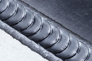
“We started the Inno-Space as a quality project,” Dr Schmidt confirms. “But now there are several projects underway.” One that again directly involves virtual rather than physical testing, and which is scheduled for implementation shortly, has seen the development of a technique in which inspection staff wear a Microsoft Hololens headset to verify that required welding operations have been carried out.
The use of a headset in this instance, he explains, simply allows the individual wearing it to keep their hands free. Again, the underlying methodology is for a computer-generated representation of a properly implemented set of procedures to be superimposed on an image of the actual car body to compare the one with the other.
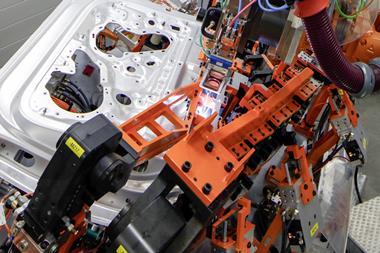
About 5,000 joining points and seven different joining technologies are involved. Every single joining point has to be checked – some within the assembly line and others afterwards. The head-up display shows the worker involved a virtual version of what would otherwise be a 300-page ‘instruction manual’, which superimposes a CAD image on that of the real-world. Within the application, the worker can check the joining points and also an interactive testing/inspection protocol. All the details of an inspection sequence are then immediately communicated to the central database.
External expertise was utilised in each case and in both projects Porsche cooperated with start-up company GTV, based in Dresden, which specialises in computerised imaging technology, and with the Fraunhofer Institute.
A vital enabling factor in both cases, Dr Schmidt explains, is that the IT infrastructure supporting the Inno-Space replicates that of the wider plant but is entirely independent of it. So, solutions can be tried out in a way that ensures their compatibility with the plant’s IT systems but runs no risk of compromising them before implementation.
Connecting with suppliers
Dr Schmidt says this system also has potential for use in the qualifying of parts before production commences – in other words, approval for use in a vehicle. At present this involves face-to-face meetings with suppliers at the production site, but if suppliers use the same system then the process can be carried out remotely with no reduction of the data accuracy that is vital to the integrity of the procedure. In practical terms, he says, this could mean that a process that can currently take a couple of days, allowing for the logistics of travel, could be reduced to just “one hour”. He confirms that this way of doing things is currently being trialled with “four or five suppliers”.
But time-saving is not the only benefit the approach brings. All the data gathered in this way, Dr Schmidt states, can be stored and made available for re-use when required. Not only does the technique represent a fusion of the virtual and real worlds, it also, he states, represents the “interface between the present and future of quality management”.
A constant in all vehicle design and manufacturing strategies is weight reduction and the substitution of metal with a plastic/composite material is a popular solution. But this poses a challenge in terms of ensuring that a new part is compatible and as such requires appropriate testing.This was precisely the issue that confronted Saudi-owned, Netherlands-based plastics manufacturer Sabic, in Bergen op Zoom, when it redesigned the metal tailgate of a car using its Noryl GTX and Stamax materials. The first of those is a PPE/PA (polyphenylene ether and polyamide) material that can provide part-weight savings of up to 50% compared with steel. The second is a polypropylene material specifically intended for automotive applications. The completed part, in which even the glass of the window was replaced by translucent polycarbonate, proved to be 30% lighter overall than its predecessor.
Part of the subsequent testing involved subjecting the part to heating in a closed climatic chamber to ascertain how it would react to thermal loading.
The tool Sabic used to achieve this was the TRITOP static deformation visual inspection system from GOM. As Wym Cuypers, technical sales representative with the Leuven, Belgium-based company explains, the system is based around a handheld camera that takes images of a part both before and after heating has taken place using as reference points multiple physical markers that have been attached to the part. The image data is then downloaded to a desktop computer where the system software can compare the two sets of images to determine what deformation, if any, has taken place.
In detail the object is prepared by fixing uncoded markers directly on to it and coded markers for picture stitching on its surroundings. In addition, scale bars are positioned near the work piece to determine the size of the object. Then the measuring technician takes a series of at least three photographs from different directions. This provides the data for the software to calculate a precise model from ray intersections, camera positions, lens distortions and object coordinates.
But, says Cuypers, the technique is not only straightforward to implement but also a practicable approach. That is because the second set of images, taken after heating, can be captured in just a few seconds after the climate chamber door is opened to allow access to the camera, so there is no time for the part to cool down and therefore distort the readings. That requirement would negate the accuracy of using coordinate measurement technology since this requires removing the part from the chamber and exposing it to ambient temperature.
Instead, Cuypers says, about 10-20 seconds will suffice to take the 15-25 photographs that might typically be required. Moreover, once the images captured by the camera are downloaded to the computer, the system software can generate a visualisation to show what has happened “in a matter of minutes”.
An alternative method does exist but it is one that in comparison would be both complex in practice and limited in effectiveness. This would involve the use of electronic devices, known as linear variable displacement transducers (LVDTs), that can be positioned on the surface of a part and used to record displacements. But, as Cuypers points out, such devices would not only require very careful positioning and wired connections, they would also only record displacements in a single direction, whereas the TRITOP methodology does so in three directions. “It can obtain x, y and z axis readings,” he states.
The efficacy of the approach is further confirmed by Marcel Rijnkels, application testing specialist with Sabic. He says the TRITOP system has been in use at SABIC since 2007, but that the tailgate project is much more recent and is still continuing. In fact, he says, the system is now used for testing various automotive parts including polycarbonate glazing, instrument panels and exterior body elements such as fenders.
“The use of an optical 3D measuring system helps in better understanding the dimensional behaviour of plastic parts,” states Rijnkels. “You can see that the current trend is changing from the more traditional type of measurement systems towards advanced optical systems.
Indeed, Rijnkels believes optical measuring techniques will be increasingly implemented in production lines as well as in R&D developments. “At Sabic we are already using it in the development phase and are also using these techniques for CAE validation,” he confirms.
Autonomous technology challenges
A type of unit that is increasingly to be found in automotive applications is radar sensors – initially as safety devices to aid drivers, but ultimately as core elements of autonomous driving capabilities. Testing of such devices is likely to become an increasing requirement for carmakers and a new piece of kit, the AREG100A radar echo generator from German-based test system manufacturer Rohde & Schwarz, is intended specifically to cater for this need on OEM and tier one supplier production lines. It can test radar sensors in the 24GHz ISM band and in the E band at 77GHz or 79GHz by simulating echoes of up to four artificial target objects at fixed distances.
According to Dr Alois Ascher, product manager, signal generators, automotive, with Rohde & Schwarz, 100% testing of this type, though not currently a mandatory requirement, is increasingly a common practice. “Most tier ones I have talked to perform 100% tests at the end of the production line to ensure proper sensor functionality. Each automotive radar sensor manufacturer has its own parameter set that is tested, so greater generalisation is difficult,” he explains. “Nevertheless, for certification, it’s like with CE, where an exemplary automotive radar sensor of a device generation has to fulfil all the mandatory regulatory parameters.”
A similar situation of manufacturers tending to exceed legislative requirements also exists with regards to testing environments. There is no mandatory stipulation, states Dr Ascher, “but because of repeatability and comparability of the measurement results, most automotive radar sensor manufacturers I know perform their end of line tests in shielded chambers.”
The AREG100A has been developed, Dr Ascher confirms in close cooperation with the automotive industry. This is reflected, for instance, in the fact that it provides “wideband E band frontend with 4GHz instantaneous bandwidth and minimum delay of the echoes for testing the most modern short-range radar sensors”. As such, he states, “the AREG is the core element of a test system. It provides artificial reference objects for the radar sensor under test, as well as calibrated interfaces at the intermediate frequency to connect additional test and measurement equipment that may be necessary to test conformance to the applicable standards.”
Interestingly Dr Ascher adds that the testing cycle time varies from manufacturer to manufacturer and could range from several seconds to several minutes per radar sensor. “It depends on the specific tests involved – for instance, measuring the antenna pattern of each radar sensor takes much more time than measuring just the boresight power level,” he explains. “Typically, the testing itself is completely automated though the loading of the test stand can either be effected manually or by a robot.”
Supplier of end-of-line (EOL) test bench equipment TeamTechnik recently extended its established range Compact Drive Testing platforms to include units intended for the testing of electric drive systems. According to Ralph Heckmann, vice-president, applications test systems, automotive, for the company, which is based in Freiberg, Germany, the testing requirements for electric drives, including hybrid transmissions and electrical drive axles, are highly specialised and require a flexible test bench concept.
“On the one hand the test benches must be designed to handle the relatively modest number of electrical vehicles produced today and also be suitable for testing different electrified drive configurations,” he explains. “On the other they must also enable EOL tests to be performed automatically on the greater numbers of electrical drives forecast for the future.”
This range of capability, though, is not concerned with the test technology itself, but with associated handling and loading procedures. For low-volume applications manual handling will suffice, but as volumes increase then automated procedures will be required.
E-drive test bench flexibility
Nevertheless, the testing of electric drives does pose some specific technical challenges in its own right that appropriate test benches must meet. For instance, the reference torques of up to 5,000Nm, and dynamic loads generated by high performance electrical drives, present challenges to mechanical components and control technology that far exceed those handled in conventional end-of-line test benches.“A test bench platform for e-drives must also be able to replicate drive outputs ranging from a 48V hybrid e-drive as a supplement to an internal combustion engine to 500kW for premium e-vehicles,” Heckmann observes. The new test benches can handle voltages up to 800V and currents up to 1,000A.
In contrast to conventional transmissions with high-precision mechanical interfaces to a combustion engine, e-drives are connected to the chassis in many different ways with high tolerances. For this reason, says Heckmann, the clamping devices in these test benches are designed with extreme horizontal and vertical flexibility to ensure test results are as non-reactive and reproducible as possible.
The test benches for e-drives also need to embody specific attributes in terms of both their physical construction and the range of sensors with which they are equipped. On the first of those counts, notes Heckmann, differences include those relating to both electrical supply and cooling water provision. On the second it means that sensors and ECUs (engine control units) must include those for electrical measurements, NVH, speed and torque controls and inverter communication.
But Heckmann indicates that the ability of this new generation of test benches to step up to the task of dealing with high-volume production environments is perhaps their most significant attribute. “The most advanced versions of these test benches are free-standing units into which the e-axles to be tested are automatically fed by a driverless conveyor system,” he states. “In addition to this autonomous automation, the comprehensive digitisation of all production and test data in line with Industry 4.0 means the concept offers completely new and unlimited ways to operate the assembly process and perform the subsequent EOL testing, including unrestricted movement to the test benches, simplified rework and repeat tests, unlimited iteration loops and shorter downtimes. In short, the concept of autonomously automating e-drive test benches is no longer merely a theoretical scenario. In fact, TeamTechnik is already implementing it in a current project.”
Like what you’ve read? Then why not become an AMS online member!
As a member you will gain full and unlimited access to our global coverage of automotive manufacturing, including our in-depth coverage of technology, OEMs, regions, suppliers, and materials. Also included are our business intelligence reports and forecasts, and we hope you will also consider joining us at one of our webinars in 2020.
We’ll also keep you up to date with regular newsletters and dedicated member only communications, so you’ll be the first to know about our latest features, reports and webinars.
To gain unlimited access to the exclusive content and features of Automotive Manufacturing Solutions please SIGN-IN or REGISTER FREE today.