The growing domination of roller hemming in automotive production, its advantages and drawbacks in comparison with other hemming techniques
In of itself, hemming as a joining technique is unexceptional. The basic concept involves folding the overlapping edge of an outer panel over the edge of an inner panel to fasten the two together. This can be accomplished in one of three ways: press hemming, in which the process takes place as a single operation in a large, fixed hydraulic press; tabletop hemming, where the hem is formed in a smaller fixed installation by the simultaneous action of electrically-actuated hemming heads; and robotic roller hemming, where the hem is formed by a roller head being manoeuvred along the edge of the combined workpiece by a robot arm.
The first two of those methodologies are well-established, the only major change being that tabletop hemming has switched from a hydraulic to an electric process. But over the last decade, robotic roller hemming has made significant inroads as a viable alternative to the other two techniques.
The difference is not so much in the end-result but in the means by which it is achieved. Press and table top hemming form the complete hem in a single operation, though they are distinguishable from each other by, for instance, their respective abilities to produce multiple parts in a single operation and the complexity of the geometries they can handle. Press hemming can achieve the former, but is more limited than tabletop hemming in the latter.
In contrast, robotic roller hemming cumulatively forms the hem as a roller head is run around the edge of the panels.
The technique therefore involves less force, since it is only applied at a single (though continuously changing) point on the panel. It is also much less demanding of ‘hard’ fixturing, though some is still required. Finally, and perhaps most fundamentally, it is an inherently flexible technique because robots are, by definition, reprogrammable devices.
The essential characteristics that favour robotic roller hemming are confirmed by Paul Meeson, Advanced Engineering Director for UK body-in-white specialists Stadco. The difference in the level of required force to achieve press hemming as opposed to robotic roller hemming is quite astounding. The former might easily involve total forces of 100-150 tonnes. But a robotic roller hemming head, says Meeson, might typically apply a force of ‘no more than a hundred kilograms’ at the point of contact.
 Stadco’s own experience with robotic roller hemming coincidentally parallels the rate at which the use of the technology has spread throughout the automotive industry. Reports Meeson, Stadco started using robotic roller hemming a little over ten years ago in the so-called ‘niche vehicles’ sector. Specifically, he recalls Aston Martin as being the first OEM for which Stadco used the technique.
In contrast, the company is currently involved in commissioning a new volume production line that has been designed and built with robotic roller hemming as a core technology. The new line is at Ford’s St Petersburg, Russia facility, in-country home to Focus production, soon to be joined by the Mondeo. At full output, the plant is expected to produce approximately 100,000 units per year. According to Meeson, numbers like these make robotic roller hemming a decidedly mainstream technique.
In fact, Meeson continues, robotic roller hemming is now likely to be the ‘approach of choice’ in almost any new vehicle manufacturing application where production volumes are upwards of 250,000 cars a year. He points to the advantages of there being no need to change the robot’s hemming head if the part being manufactured is changed. In that case, he notes, “all you have to change is the lower bed.”
Meeson points out that above production volumes of 250,000, modern electric tabletop hemming systems tend to reassert themselves, as robotic roller hemming runs up against one of its inherent constraints. The underlying operational factor, he explains, is that below that volume, the lower bed change tool switch can be accomplished within the cycle time of the overall process. Above that, the situation is reversed and the cycle time is too short. In contrast, press hemming is increasingly confined to the production of ‘legacy’ parts for after market sales– appropriate, given that it was likely the method used to make the original part.
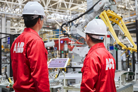
A company that has made a major business out of the provision of robotic roller hemming installations is ABB.
Robert Low, UK-based account manager for ABB, says that the company invented the process, though as it does not hold any patents on the technique, it remains open for free usage. He adds that currently, the procedure can operate at a maximum traverse speed of around 1,000mm/sec, though in practice, most installations tend to run at a reduced rate of 500-600mm/sec.
 Developments of ABB’s capabilities in the field are masterminded in France’s Saint Ouen L’Aumone, about 30 miles north-west of Paris, where the company maintains a research centre for body-in-white technologies. François Malatier, Closures Business Development Manager, confirms that the company has various initiatives underway to further develop the technique. One idea, he says, is to find ways to apply the technique at higher production volumes. “We are now trying to use multiple robots to achieve rates of eighty parts per hour,” says Malatier.
Another factor that can inhibit the effectiveness of the technique is part geometry. Robotic roller hemming, Malatier admits, may not be applicable in particularly constricted areas of assembly, such as a window channel.
But for the moment at least, that seems to be an intrinsic constraint that cannot be evaded. As it is, adds Malatier, robotic roller hemming still needs a robot with at least six axes of movement, though apart from that, the application makes no particular demands in terms of robotic technology. “Any general purpose robot with six axes of movement and a load capacity over a hundred and fifty kilograms will be suitable,” he says.
The most interesting technology in robotic roller hemming concerns the hemming head. Within this unit there are various levels of sophistication available. Some heads are rigid, while others use either a mechanical spring or an air suspension system to allow an enhanced degree of force control when the head is in contact with the assembly during the hemming process.
Malatier says that there are still apparently fundamental aspects of the approach that may be subject to change. One of these concerns the jigs for holding parts that can act as an inhibitor of the technique’s utility at higher production volumes. Malatier goes on to say that the radical idea with which ABB is currently experimenting is getting rid of the jig altogether. He does not go into detail of how this might be achieved, but will concede that the company ‘has done some tests’.
Meanwhile, another company that develops and implements hemming solutions is DV Automation. Indeed, the company’s business manager Mark Schlanker describes the provision of hemming systems as the operation’s main activity. Nor is the company new to the area. Schlanker says that around 20 years ago, DVA was the first to offer tabletop systems equipped with an electric drive mechanism.
Schlanker also says that in the recent past, he has noticed a change in market demands, with a growing interest in the use of tabletop hemming systems, particularly for parts such as bonnets. He suggests that it is the seemingly remorseless expansion in the use of robotic roller hemming over the last decade that has pushed it into areas where the associated tooling demands are offsetting the market appeal of its flexibility and reprogrammability. The consequence is a blurring of the previous distinctions between the two techniques.
That convergence is not something that DVA necessarily regards as unwelcome. In 2008, the company introduced a new product specifically aiming, as Schlanker says, “to combine the quality and robustness of tabletop machines with the ease of use of robotic roller hemming.”
The device, named Flex Hemmer, is essentially a tabletop machine that makes use of an interchangeable cassette based tooling system that allows quick and easy changeover between parts. Various options are available to adapt the device to suit particular requirements, including a component-indexing shuttle and a robot gripper that docks onto the tooling head.
In short, it appears that although the fundamentals of hemming are fixed, the technology is still capable of supporting quite considerable enhancement and innovation. Moreover, the companies that are supplying systems to the automotive sector are actively pursuing strategies of continuous and on-going improvement.
 On the other hand, clinching is a straightforward and highly-effective technique for joining sheet metal. It involves using a specialised punching tool to push one metal sheet into but not through another, with the resulting join expanded using hydraulic or hydro-pneumatic actuation to form a type of ‘press stud’ between the two pieces of metal.
The result is a durable join achieved without puncturing either sheet and without the addition of any further weight – there are no fasteners involved of any sort.
One of the best-known forms of clinching is the Tog-LLoc system from US company BTM. According to Mark Firmin, Managing Director of the company’s UK operation, the technique provides a cheaper but less robust alternative to spot-welding. “If you compared our system to spot welding on a like-for-like basis, then the Tog-L-Loc would be about twenty per cent less strong,” he says.
On the other hand, the technique offers environmental and material advantages. On the first count, it requires no heat and produces no fumes during application. On the second, it does not destroy surface coatings, though these will obviously be thinned over the area forced to expand.
“It does not expose the bare surface of the metal,” confirms Firmin. Firmin goes on to say that the system has been widely used as a fastening technique throughout the automotive industry. Components involved include bonnets, boots, brake pedal brackets, roof bows, sunroof frames, gaskets, heat shields, gas tank straps, air conditioning tubes and airbag housings. One particular capability of the technique that Firmin pinpoints is the ease with which it can be used to join dissimilar materials. On early models of the Land Rover Discovery, clinching was used to fasten aluminium to steel in the rear door assembly, though that particular application is no longer current.
Improved strength characteristics
Looking to the future, the area into which clinching might be able to expand is that of more arduous applications subject to greater load forces. Given that the technique itself is conceptually static, that would have to mean applying it to materials harder than the mild steels and aluminium with which it is commonly employed today.
 One organisation that is investigating that potential is U.S. Steel. Based at the organization’s offices in Troy, Michigan, Jody Shaw, Technical Marketing and Product Research Manager says that tests have shown that mild steel spot welding is about three times more resistant to sheer than clinching, though roughly equivalent in resistance to peeling. That is why clinching has not so far been employed in body structures, observes Shaw, but instead in ancillary fabrications such as sunroofs and gloveboxes. But he adds that U.S. Steel has been working over the past couple of years to explore the possibilities for applying clinching techniques to advanced high strength steels. In fact, the work has been advancing through in cooperation with BTM.
Shaw says that while mild steel has a strength in the order of 200 Megapascals (MPa), the newer materials on which the work has focussed may be three, four or even five times as strong. At present, he says, he is unaware of any relevant applications involving the clinching of such materials.


