


Coherent-ROFIN’s Frank Gäbler describes how the CleanWeld process can garner greater results in fibre laser welding
While automotive manufacturers have successfully employed fibre lasers in metal welding for over a decade, efforts still continue to improve their utility and extend the results they deliver in terms of part quality, production throughput and process costs. Increasingly, automotive suppliers look to the laser or laser system manufacturer to lead this effort, often by providing a complete solution rather than just a laser. This can include the beam delivery optics and process head, control software, and even the “process recipe” that delivers the optimum results for the particular application.
Within Coherent (now including the former ROFIN-SINAR industrial laser group) this has resulted in several innovations in welding applications, with a particular focus on delivering a better fibre laser-based welding process to customers, rather than simply a better fibre laser. Specifically, a Coherent program called CleanWeld targets developing fibre laser welding processes with reduced spatter and cracking, less porosity, improved process consistency, and reduced cost across many different welding applications. This article reviews how the CleanWeld approach has been successfully applied in three important areas, namely powertrain components, hang-on parts and zero gap galvanised steel welding.
Key laser welding parameters
Most automotive laser welding applications can be classified as keyhole, or deep penetration welds. Here, the laser is focused to achieve a very high power density so that the metal actually vaporises – this vaporised metal element extends into the material creating the keyhole that is surrounded by the melt pool. Vapour pressure within the keyhole from the laser beam absorption prevents closure by the pressure from the melt pool. The focused laser beam and keyhole continuously move along the welding path.
The quality of a weld is determined by the stability of the keyhole during the welding process. The goal is to achieve an energy balance between the absorbed laser power in the keyhole that is maintained through its depth to ensure uniform absorption and non-perturbed molten flow around the keyhole. This in turn provides consistent weld depth and, more importantly, minimised spatter and porosity.
To date, achieving an acceptable level of weld quality and reliability using fibre laser technology has been possible, but certainly not ideal, as one of the defining factors for this laser source is its high beam quality which is great for cutting but less than ideal for penetration welding. Mitigating this high brightness can be achieved using multi-mode fibres and defocusing the laser into the workpiece, or possibly using a wobble head. The following examples illustrate some specific applications that can benefit from modifying the typical focused intensity distribution of a fibre laser.
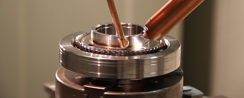
 Figure 1: Fibre laser and CO2 laser welding of powertrain gears show essentially identical results – a deep penetration weld with good aspect ratio and no spatter. Both welds were done at the same feed rate of 3 m/min
Powertrain component welding
Welding of powertrain coupling components has long presented a challenge for fibre lasers, specifically because these lasers typically produce some spatter. This type of contamination is particularly unacceptable on powertrain gears or bearing surfaces. Furthermore, spatter is often accompanied by weld porosity (since the spattered material may leave a void or an undercut), which can affect weld quality, strength and consistency.
Applications development work at Coherent employing the CleanWeld approach has proven that spatter can be largely eliminated even using a fibre laser. While the specifics involved optimisation of multiple process factors, including laser power and gas delivery nozzles, probably the biggest improvement came from choosing the right delivery fibre. In particular, changing the focused beam profile away from the standard simple Gaussian produced a substantial reduction in turbulence in the melt pool, which then reduces spatter. Sample welds (figure 1) confirm the quality of the optimised fibre laser welding process.
Figure 1 shows a narrow welding seam (width < 1mm), which is useful when part dimensions are accurate (e.g. zero gap). This delivers minimal heat affected zone and distortion. The root width remains > 0.3mm, similar to a CO2 laser weld. However, some powertrain welding applications have to bridge gaps, due to part inaccuracies. By smart adjustment of the optical set-up, gaps of up to 0.3mm can be bridged (without filler) by using a very calm weld with very little spatter and porosity (see figure 2).
In addition to eliminating spatter, the fibre laser welding parameters used in this case also enabled higher speed processing. In fact, one automotive supplier who has utilised this technique stated that their throughput had increased by 20% over their previous fibre laser process.
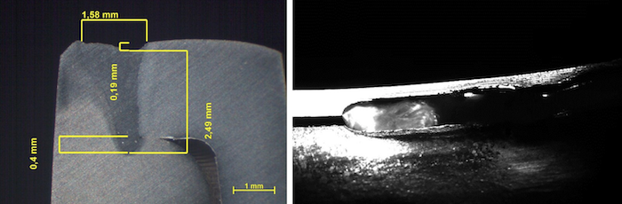 Figure 2: CleanWeld setup to weld components with gaps of up to 0.3 mm without filler wire in a very calm welding process
Hang-on parts welding
Hang-on parts, which frequently incorporate aluminium, also present difficulties for laser welding. In particular, aluminium has a tendency to “hot crack” because of loss of its alloying elements during welding usually. This creates the need to add material into the melt pool, typically in the form of filler wire. Additionally, spatter is sometimes problematic for hang-on parts since it introduces contamination which can get trapped within an assembly (such as a door). For example, one manufacturer reported problems with spattered material subsequently migrating to and blocking door draining holes.
The CleanWeld solution in this case again involved utilising a dedicated intensity distribution in the focused laser spot. The optimised beam shape allows the part to be both pre- and post-heated, thus avoiding problems caused by rapid part cooling. It also eliminates spatter and the need to use filler wire. The results, and effectiveness of subtle changes in laser power distribution, are shown in figure 3. Parts A and B show that, by adjusting the beam intensity profile, the depth of weld can be controlled while keeping the weld width constant.
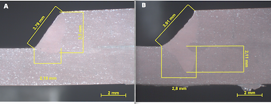 Figure 3: These two fillet weld cross sections show the dramatic effect of changes in weld results with just minor adjustments in focused spot intensity distribution. In the first sample (A), the weld does not penetrate well into the bottom piece. A slight change in the intensity profile, which increased the pre- and post-heating effect, produced a weld (B) with excellent penetration, at the same feed rate of 5m/min
Welding zinc coated steel with zero gap
Galvanised steel is another material widely used in hang-on parts, as well as in bodies. Zero-gap lap welding of this material has presented a challenge for laser welding because the more volatile zinc evaporates first when the laser energy is applied to the material. This creates gas pressure which can blow out the molten steel, resulting in an inconsistent weld seam, as well as spatter that needs to be subsequently cleaned. This problem can be mitigated by either dimpling the material, or adding spacers between the metal sheets, so that there is sufficient space (~ 0.1- 0.5 mm) for the vaporised zinc to vent in a controlled manner to the side, rather than the top, of the keyhole. But this approach has drawbacks.
The CleanWeld approach has proven the ability to perform galvanised steel welding without the need for a gap between the parts. Once more, much of the laser power is distributed away from the beam centre and into the edges. As with aluminium, this approach both pre- and post-heats the material, and also reduces the pressure at the centre of the keyhole. This allows the zinc gas to vent out easily through the centre without producing any spatter, even when the parts are clamped together with zero gap. However, it’s worth noting that this power distribution is symmetric, so the orientation of the beam doesn’t have to be changed to follow the direction of the weld seam, which might vary substantially on a contoured or shaped part. This greatly simplifies its implementation and can be done by using a scanner head.
As fibre laser themselves become a mature technology, further improvements in fibre laser welding are most likely to come from a better understanding, and control, of the factors which influence exactly how laser energy is applied to the workpiece. The CleanWeld effort at Coherent has already proven that dramatic improvements in weld seam geometry, spatter, cracking, porosity and process stability can all be achieved by using existing fibre lasers more effectively.